HARDWARE / XIAO ESP32-C3
A clear view of
every connection.
The updated schematic and routed PCB for the pressure sensor carrier. Now specified with manufacturer part numbers and the actual XIAO footprint. Inspect the design, then download the Altium project and local libraries.
DESIGN EXPLORER
Follow the signal.
Readable signal paths
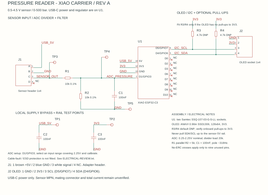
Continuous sensor, divider, filter and I2C connections. Bypass capacitors and test points sit beside their related circuits.
Connectivity checked
All 32 connected pins match the PCB’s seven nets. Nine intentionally unused pins remain marked NC.
MANUFACTURER PARTS
Specified. Sourced. Editable.
Download BOM ?| Reference | Manufacturer | Part number | Specification |
|---|---|---|---|
| U1 | Seeed Studio | 113991054 ? | XIAO ESP32-C3 |
| U1 sockets (2) | Samtec | SSQ-107-03-G-S-LL | Removable XIAO, two 1x7 sockets |
| J1 | Samtec | TSW-104-07-T-S ? | Sensor header 1x4 |
| J2 | Samtec | SSQ-104-03-G-S-LL ? | OLED socket 1x4 |
| R1, R2 | YAGEO | RT0603BRD0710KL ? | 10k 0.1% |
| R3, R4 | YAGEO | AC0603FR-074K7L ? | 4.7k 1% DNP |
| C1, C2, C3 | TDK | C1608X7R1H104K080AA ? | 100nF 50V X7R |
The XIAO uses Seeed's through-hole footprint with two specified Samtec sockets. TP1?TP5 are bare PCB test pads. R3/R4 remain optional. The reference build identifies an ANAVI 0.96-inch SSD1306 OLED: GND, VCC, SCL, SDA; SCL connects to D5/GPIO7 and SDA to D4/GPIO6. Sensor wiring is brown +5V, blue GND, white signal, as described in the Spectronik manual. The individual sensor part number and photographed Molex series are not specified by the reference. J1 remains a specified 2.54 mm adapter header; physical mating still needs verification. Download reference comparison.
EDITABLE SOURCE
Your next revision starts here.
Extract the ZIP and open the .PrjPcb file in Altium Designer. The schematic and PCB are included in one project.
Design draft · Altium compile passed; PCB DRC and hardware checks outstanding